Fruit Equipment Engineering, Installation and Supply
Bring the machine structure, product path and installation requirements into one equipment specification.
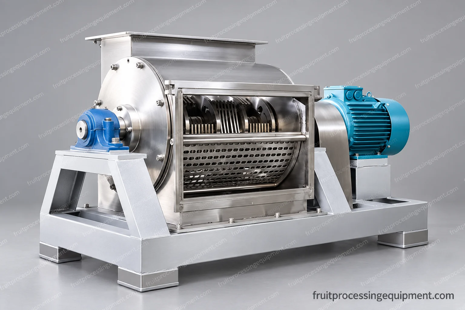
Working chamber shown open for isolated inspection. Covers and guards are fitted for operation.
Working assemblies
Begin with the physical machine.
The open crusher chamber shows the rotor, perforated section, shaft and external drive. The pulper has two independently driven stages; the thermal and cleaning systems combine vessels, exchangers and valves. These different structures need different access, connection and maintenance arrangements.
Record the condition of the product at each machine inlet and outlet. Conveyor discharge height, hopper presentation, pump inlet conditions, valve passages and tank working level affect whether adjacent equipment can operate together.
Layout and access
The general arrangement places machines, walkways and service zones in the available area. Rotor withdrawal, screen removal, drive service and vessel-port access need room beyond the static footprint. Installation drawings define the actual interfaces and anchoring requirements.
Process integration
Utilities and controls
Separate product flow from heating, cooling, vacuum, air and cleaning-service requirements. Connected equipment should respond coherently to low level, blocked discharge, downstream stoppage and a process outside its operating conditions.
Cleaning matrix
Name each closed circuit and its return route. Record components that need opening or removal separately. The CIP skid supplies selected services; the connected pipework, valves and equipment determine whether those services reach the intended surfaces.
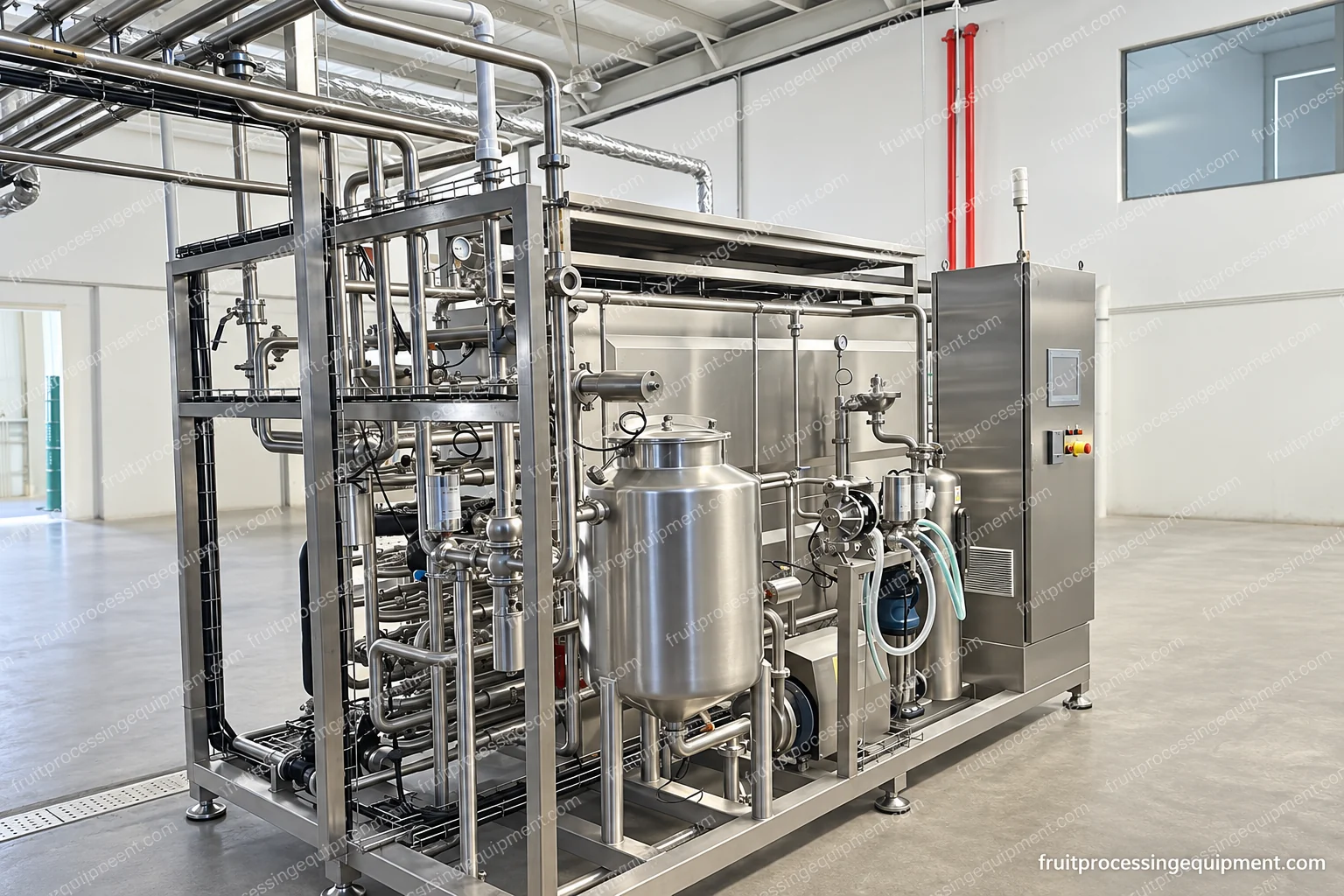
Connected thermal equipment arrangement. The treatment duty and downstream boundary are product-specific.
Equipment preparation
Inspect assemblies and establish acceptance.
The connected skid view shows equipment structure and service access. Product-specific testing adds the actual feed condition, operating settings and measured output to that inspection. Scope documents distinguish an assembly check from a process trial and from a site acceptance run.
Include the selected checks, drawings, operating instructions and any agreed installation or training work in the supply schedule. For a connected system, define each machine check, product trial and site integration check separately, including the test conditions and acceptance criteria.
Replacing one machine
Start from the existing upstream and downstream boundaries. A larger replacement does not automatically increase line output: storage, heating, filling and cleaning time can remain limiting. Check both steady operation and start/stop transitions.
An equipment enquiry can start simply
Send the fruit, wanted product and the machine or section you need. If available, add existing-machine details, required rate with units, package information and a layout. The scope can then be developed around the real interfaces.